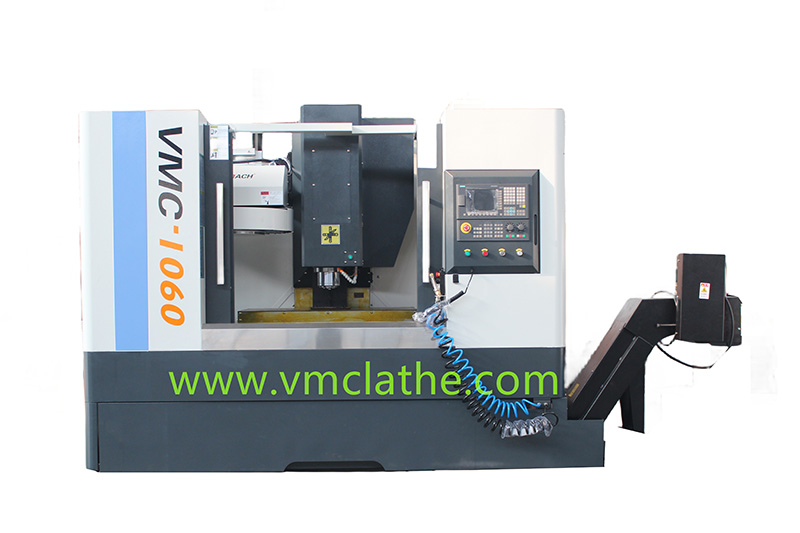
Machining an engine cylinder block on a machining center requires key steps, including clamping and positioning, top surface machining, cylinder bore machining, crankshaft hole machining, and quality inspection. These steps are as follows:
1. Clamping and Positioning:
After the cylinder block is loaded onto the machining center worktable, an air check is first performed to verify that the workpiece is level. After this check, a custom fixture on the worktable, powered by hydraulic oil, clamps the workpiece to ensure stability during machining. Clamping and positioning are designed according to the product drawing, typically using the bottom surface and two locating pin holes on the bottom surface as reference points to eliminate accuracy errors caused by datum shifting.
2. Top Surface Machining:
A. Roughing and Semi-finishing: A disc milling cutter is used to perform rough and semi-finishing milling on the cylinder block top surface to remove most of the stock.
B. Finishing Milling: A specialized milling cutter, such as a 250mm diameter Kyocera disc milling cutter, equipped with PCD cutting edges and wiper blades, is used to complete the top surface finish in a single pass. During the fine milling process, cutting parameters and tool paths must be controlled to improve machining accuracy and surface quality.
C. Deburring: After fine milling, use a nylon brush to brush around the top surface to remove burrs and improve milling roughness.
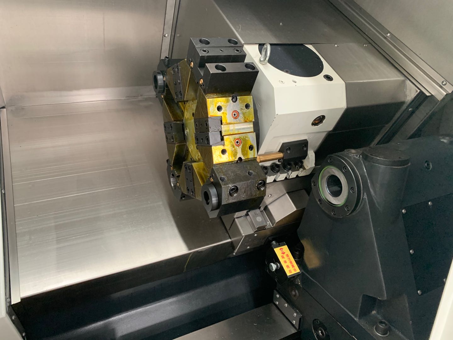
3. Cylinder Bore Machining:
A. Rough Boring: Use a rough boring tool to rough-machine the cylinder bore, removing most of the excess stock.
B. Fine Boring: Use a specialized fine boring tool, such as one with internal coolant, to fine-machine the cylinder bore. During fine boring, cutting parameters and tool wear must be controlled to ensure dimensional accuracy and surface quality.
C. Honing: After fine boring, the cylinder block is honed on a honing machine to further improve the cylinder bore’s cylindricity, straightness, and surface finish.
4. Crankshaft Bore Machining:
A. Rough Machining: Use a rough boring tool to rough-machine the crankshaft bore.
B. Semi-finishing and Finishing: Specialized boring tools, such as combination boring tools, are used to semi-finish and finish the crankshaft bore. During the finishing process, cutting parameters and tool wear must be controlled to ensure the dimensional accuracy and surface quality of the crankshaft bore.
C. Reaming: For electronically controlled engine cylinder blocks, the crankshaft bore requires reaming after finish boring to improve its roundness, straightness, and surface finish.
5. Quality Inspection:
A. Dimensional Inspection: Dimensions of key areas, such as the cylinder block top surface, cylinder bore, and crankshaft bore, are inspected using equipment such as a coordinate measuring machine (CMM) to ensure compliance with design requirements.
B. Surface Quality Inspection: The cylinder block surface quality is inspected through visual and tactile inspection to ensure the absence of defects such as scratches and burrs.
C. Sealing Inspection: The cylinder block is subjected to a sealing inspection, such as a leak test, to ensure no leakage.