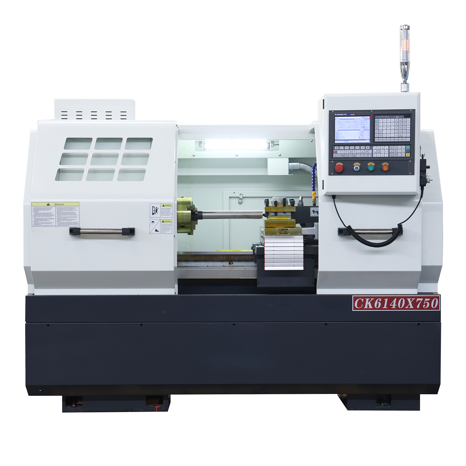
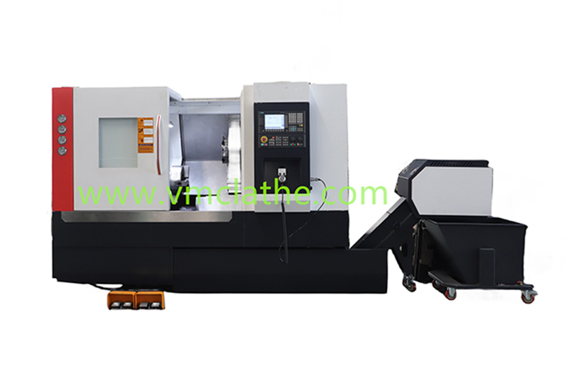
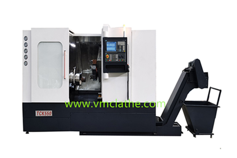
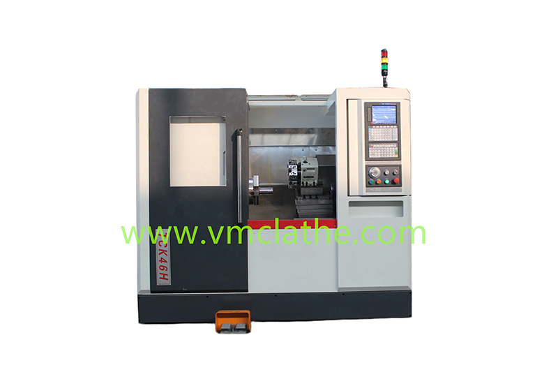
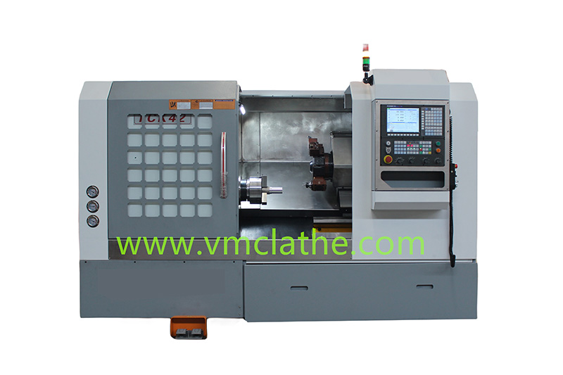
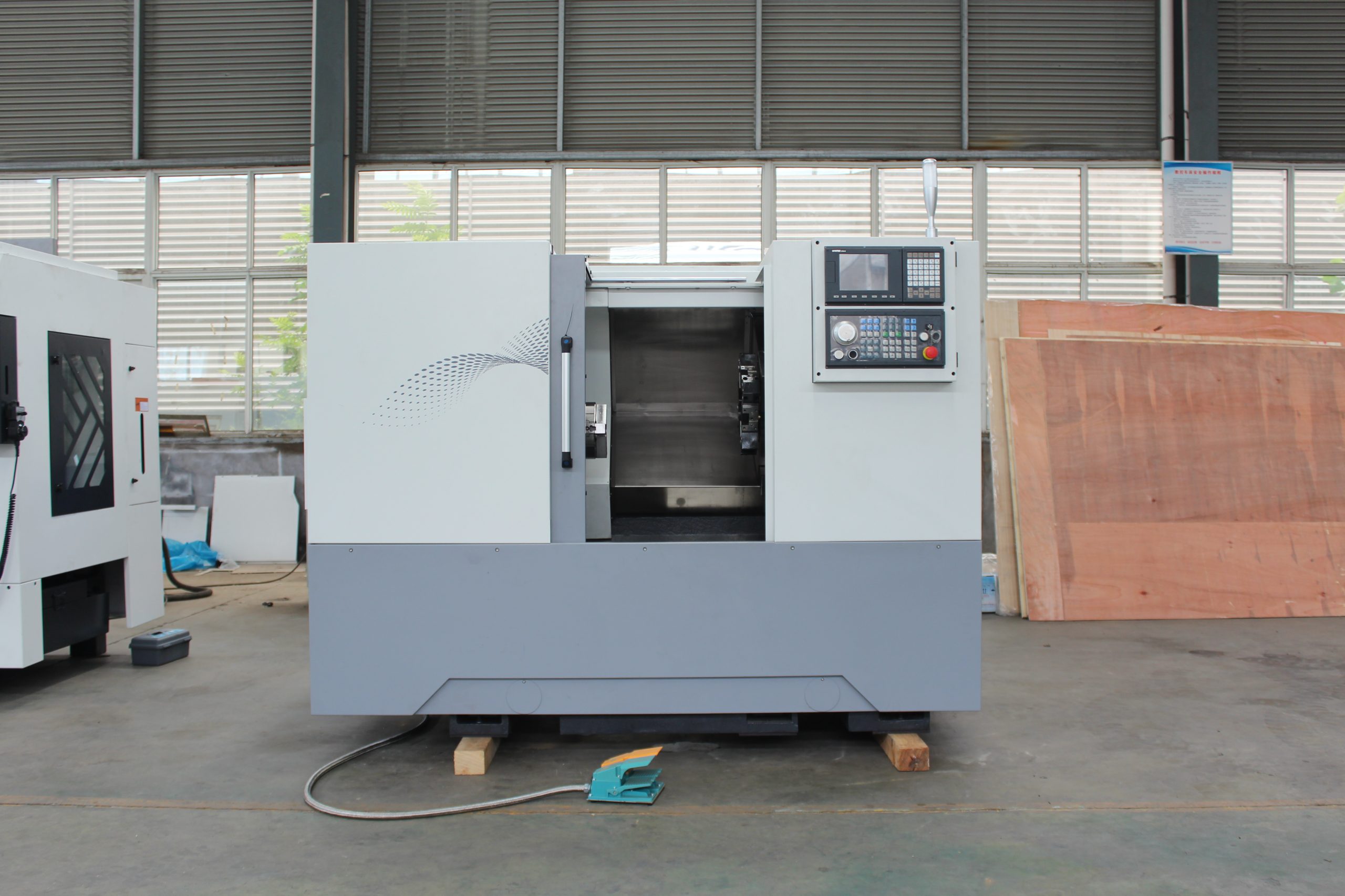
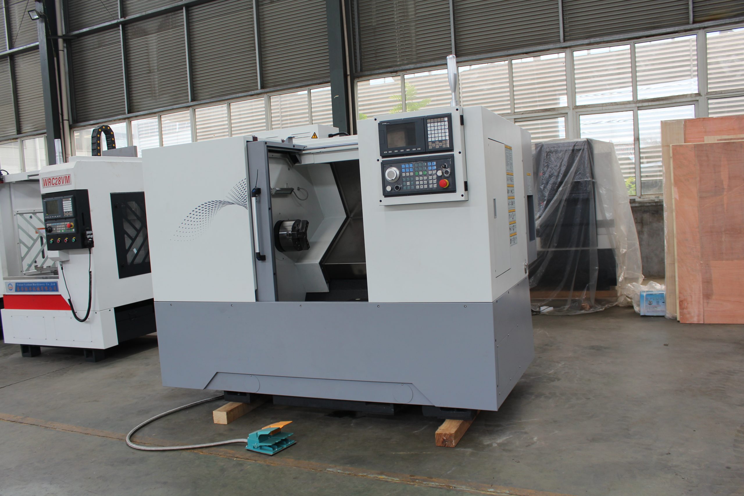
Slant-Bed CNC Lathes, with their high rigidity, high precision, optimized cutting performance, and spacious machining area, have become core equipment for shaft processing. They are particularly suitable for the efficient production of precision shaft parts such as drive shafts, spindles, and rotor shafts. The following analysis focuses on four dimensions: technical advantages, machining range, typical applications, and process optimization:
1. Technical Advantages: The Core Value of the Slant-Bed Design
A. Cutting Vibration Suppression
The slanted-bed structure (typically tilted 30°-45°) aligns the direction of cutting forces with the direction of guideway forces. Combined with the highly rigid cast iron bed, this effectively reduces vibration. For example, when machining long shaft parts, vibration amplitude can be reduced by over 30%, ensuring a surface roughness of Ra ≤ 0.8μm.
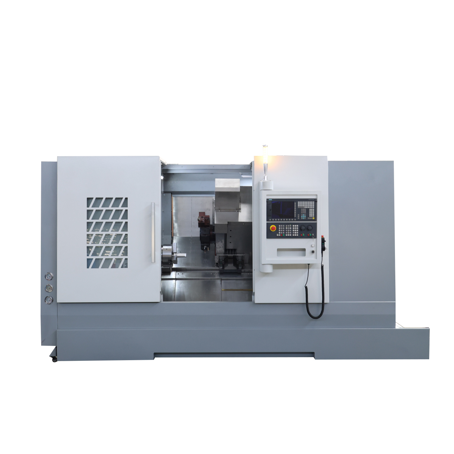
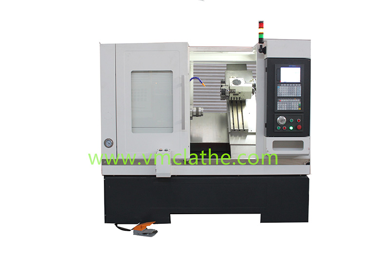
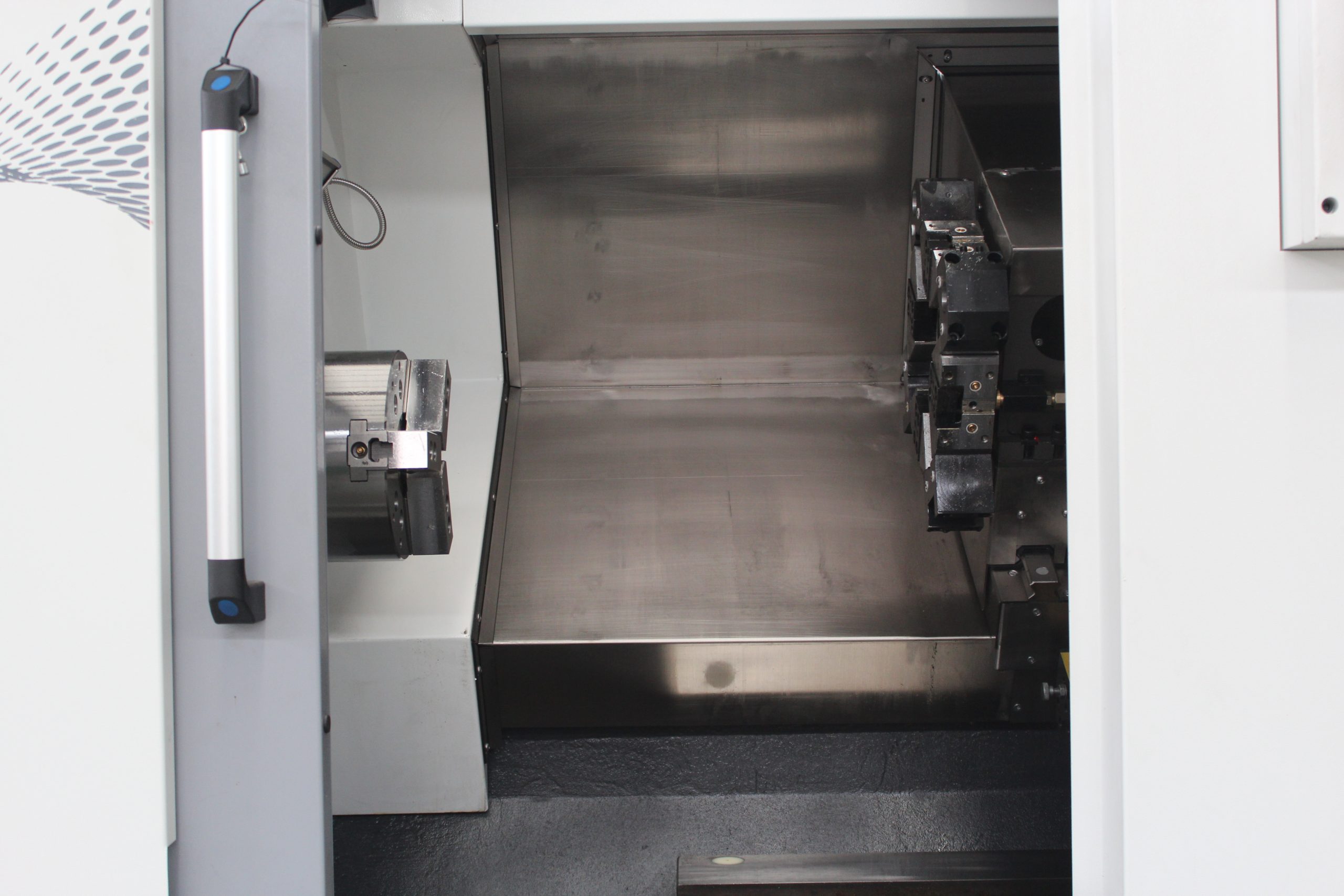
B. Efficient Chip Evacuation
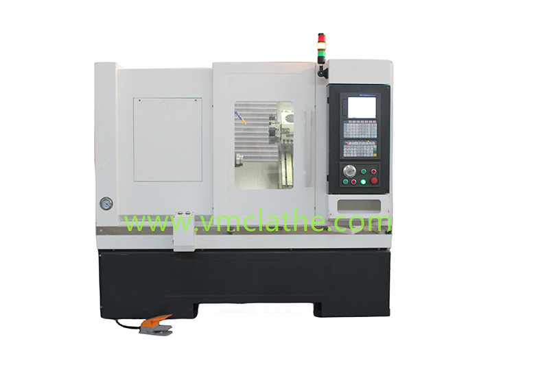
The slanted-bed design allows chips to flow naturally, preventing accumulation in the machining area. In turning-instead-of-grinding processes, timely chip evacuation reduces secondary cutting damage and improves surface quality. It is particularly suitable for the fine machining of shaft parts with a hardness of HRC 50 or higher after quenching. C. Optimized Tool Entry Angle
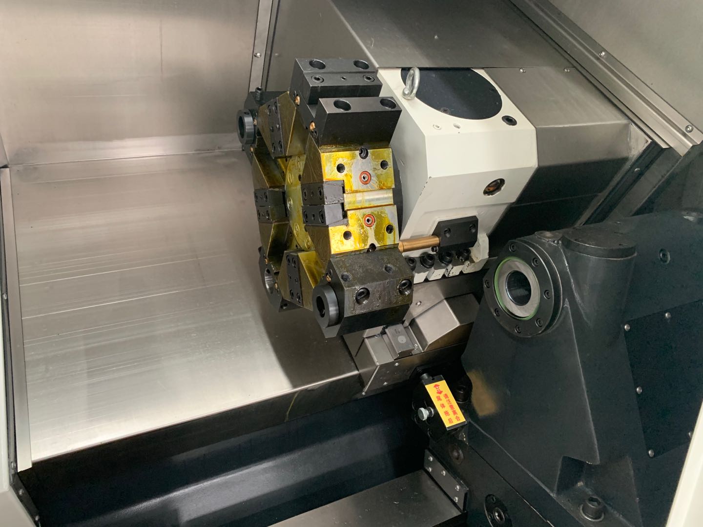
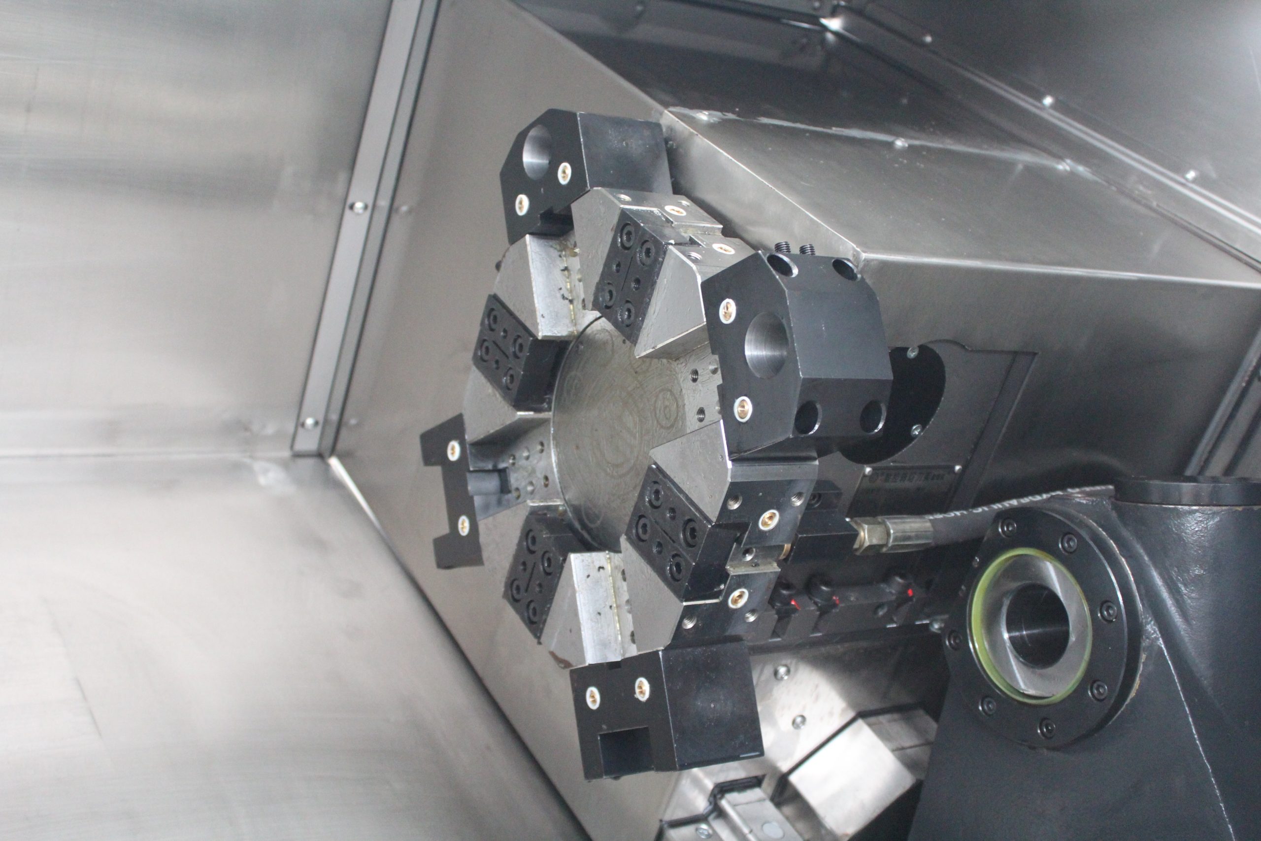
The slanted bed structure provides a more optimal tool entry angle, reducing cutting resistance. For example, when machining crankshafts, adjusting the hydraulic pump pressure to 18 MPa stabilizes tool turret motion accuracy, prevents tool movement, and ensures a journal roundness tolerance of ≤0.005mm.
2. Processing Scope: Covers all types of shaft parts
A. Standard Shaft Parts
a) Drive Shafts: For example, automotive drive shafts require integrated machining of the external diameter, end face, chamfer, and keyway. Slanted bed CNC lathes utilize a multi-station turret toolholder for local tool change, achieving positioning accuracy ≤0.005mm and tool change time ≤2 seconds.
b) Spindle: For example, machine tool spindles require high-precision through-hole structures. The slanted bed design, combined with a spindle servo motor with a 1:3 transmission ratio, achieves high torque at low speeds (e.g., a stable cutting force of over 5000N at spindle speeds of 60-800 rpm). B. Complex Shaft Parts
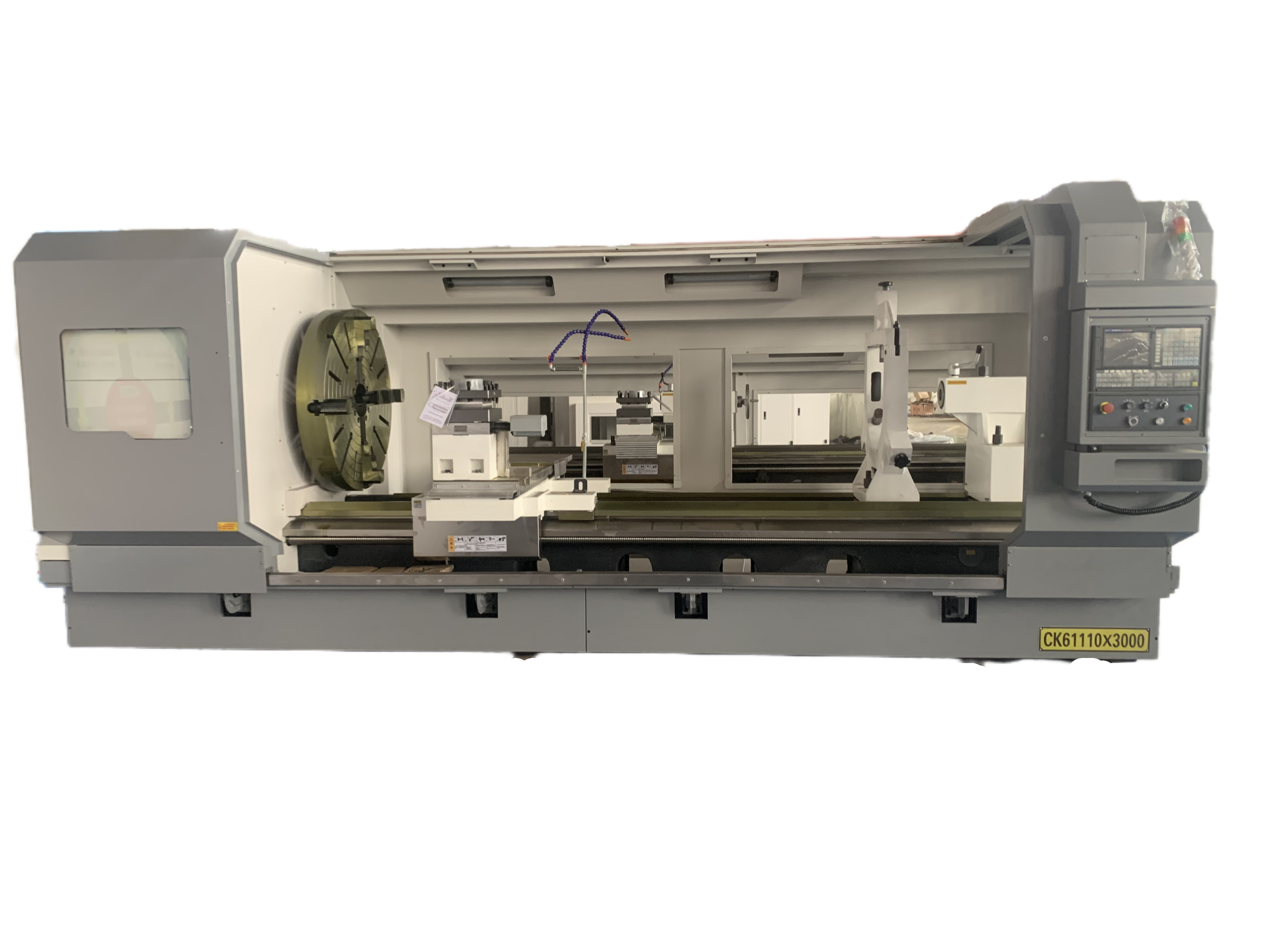
a) Crankshafts: Automotive engine crankshafts require balanced journal roundness and surface smoothness. Slant-bed CNC lathes utilize a V-shaped steady rest and roller carriage to compensate for springback errors caused by an overhang of 400mm, ensuring a straightness of ≤0.01mm for each journal.
b) Special-shaped Shafts: For shaft parts with spiral grooves, slant-bed CNC lathes automatically switch tool feed paths through macro programs, enabling continuous machining of C1.5 arcs and avoiding repeated tool skipping caused by manual programming.
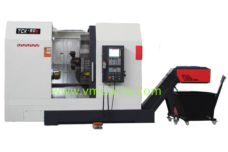
3. Typical Applications: Industry Case Studies
A. Automotive Industry
a) Case Study: An automotive parts manufacturer uses a slant-bed CNC lathe to machine crankshafts. By utilizing a four-station CNC toolholder equipped with an R-shaped chip breaker, milling efficiency at the root of the counterweight increased by 40%, extending tool life from 85 to 280 pieces. B. Aerospace
a) Case Study: Machining aircraft engine spindles. The highly rigid guideways of the inclined-bed machine tool (the Z-axis utilizes a six-slide design) and a pre-tensioned, internally recirculating ball screw nut achieve spindle runout of ≤0.003mm, ensuring machining accuracy in compliance with ISO 230-3 standards.