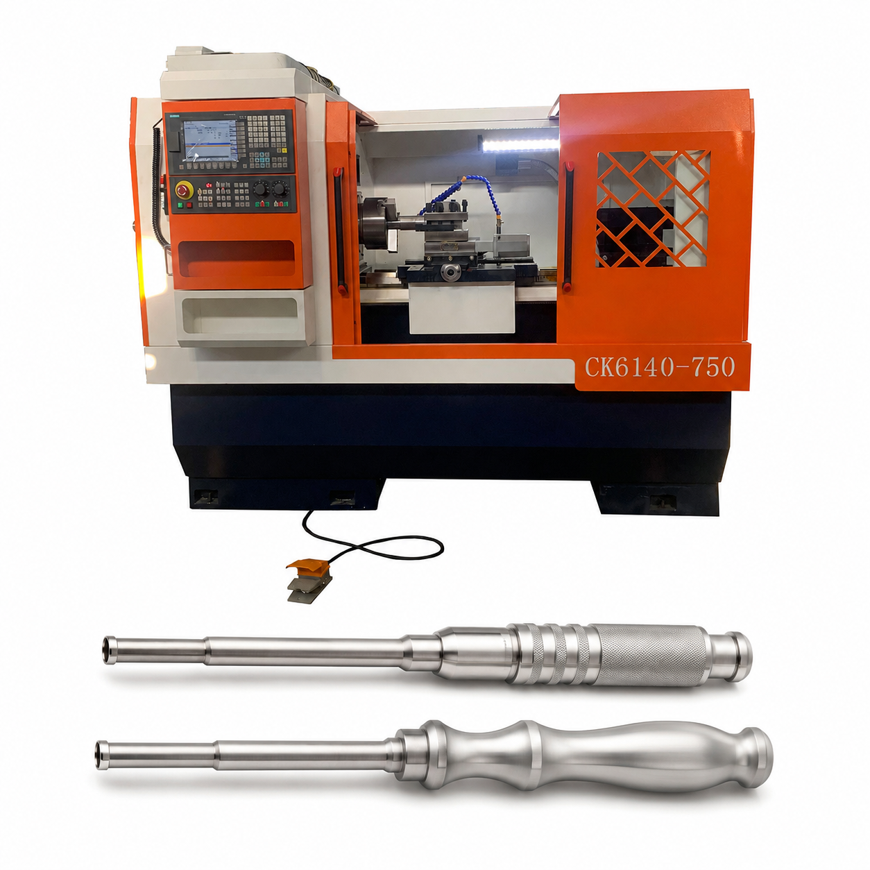
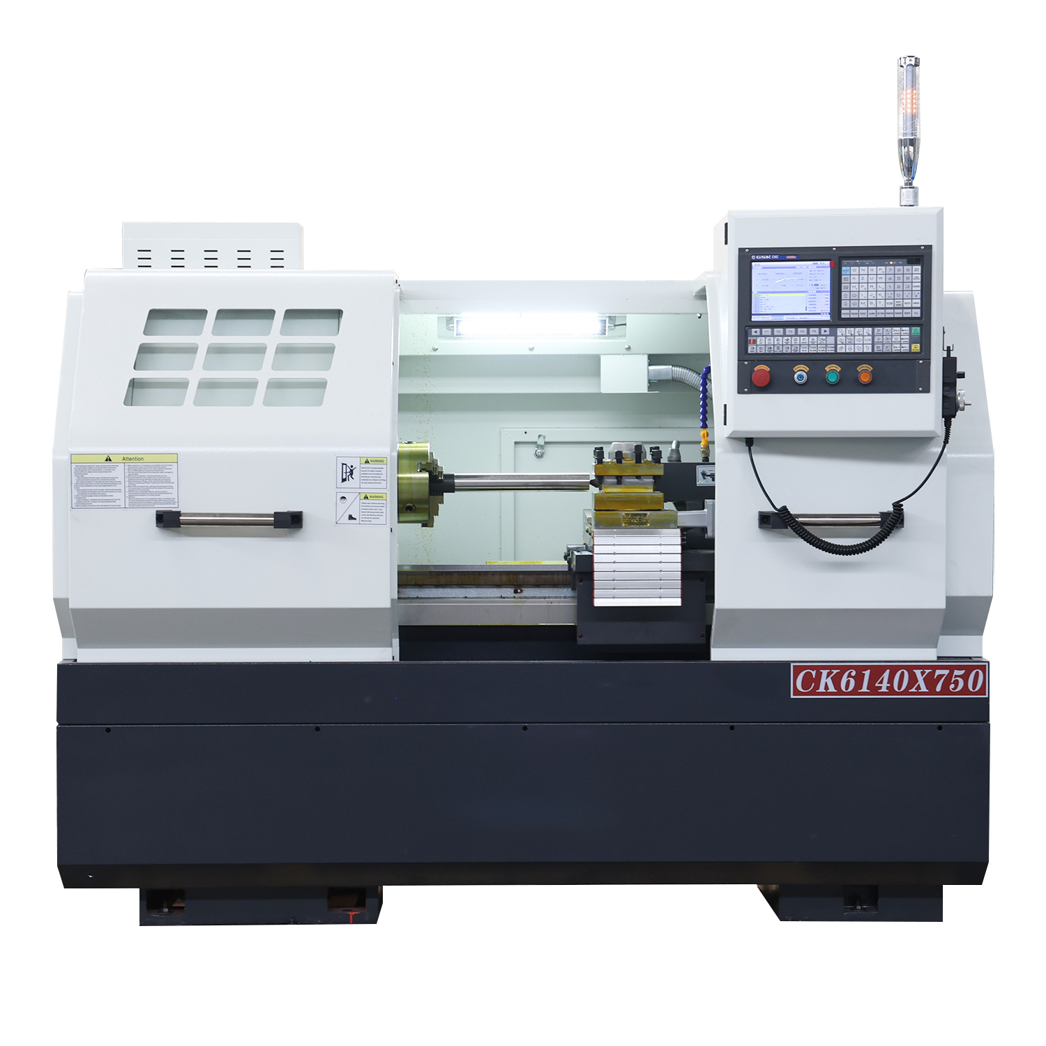
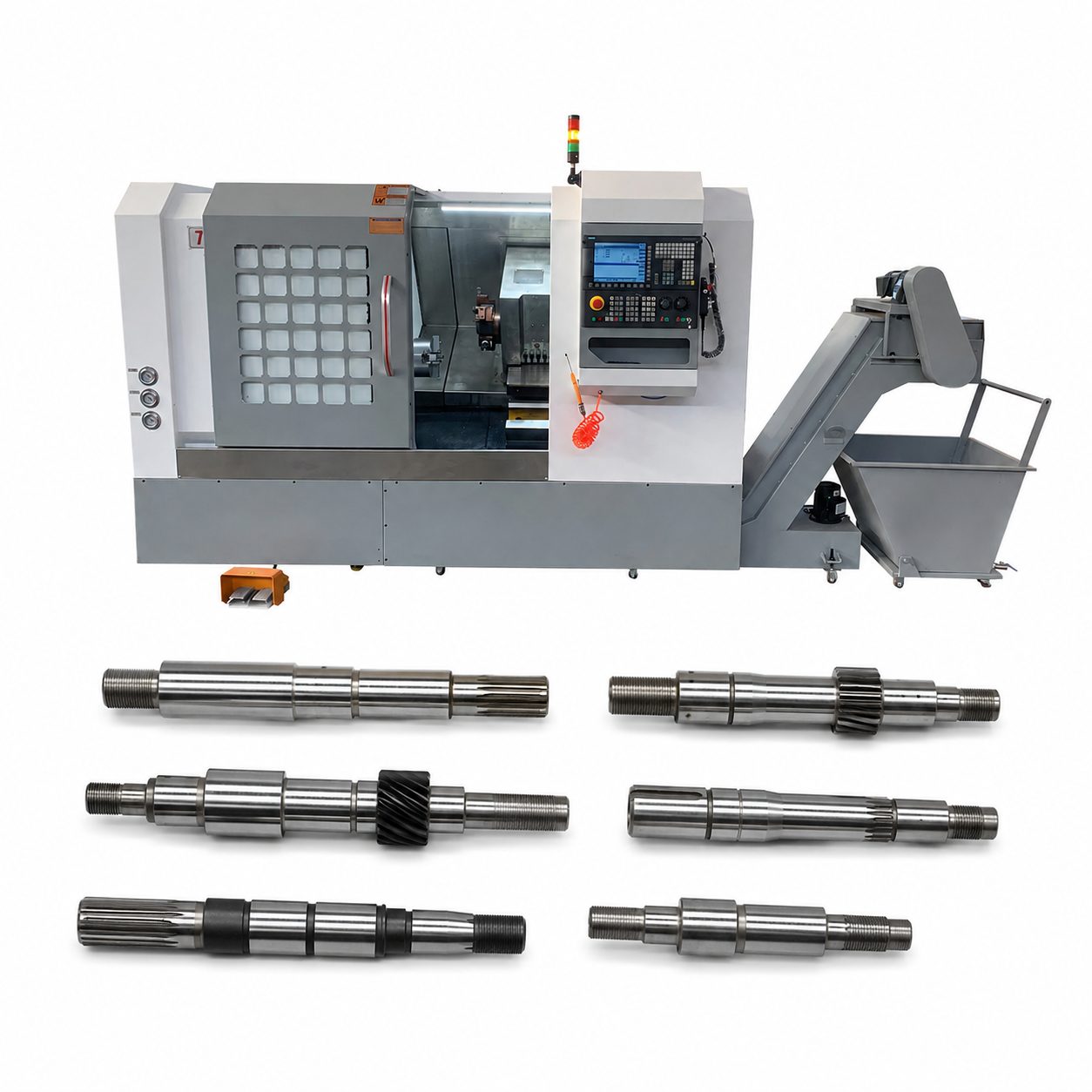
In the field of precision machining, drive shafts serve as core components in industries such as automotive, engineering machinery, shipbuilding, and power equipment. They demand exceptionally high standards for machining accuracy, surface roughness, and production efficiency. The answer is an absolute yes: slant-bed CNC lathes can not only machine drive shafts but are also the premier choice for the mass production of high-precision drive shafts.
This article delivers an in-depth analysis of the unique advantages of using a slant-bed CNC lathe for drive shaft machining and breaks down the complete manufacturing workflow step by step.
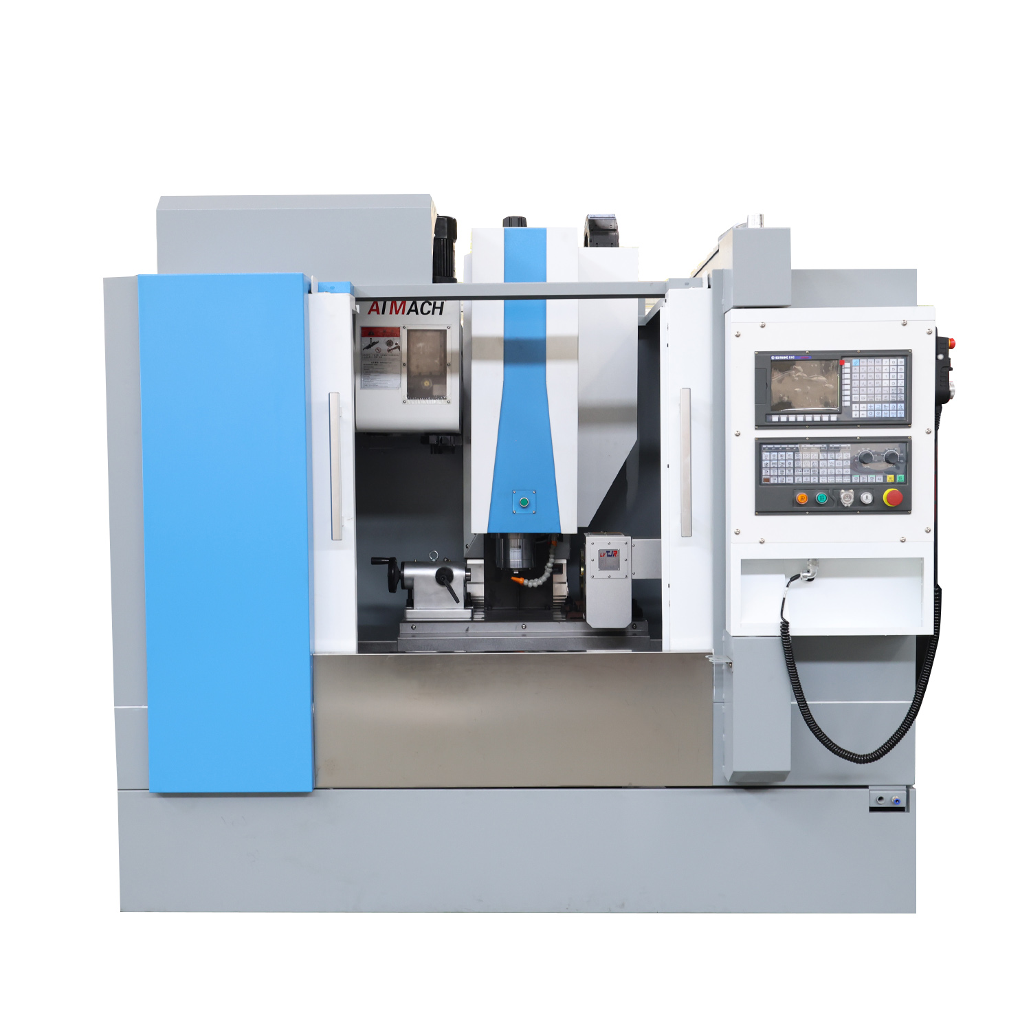
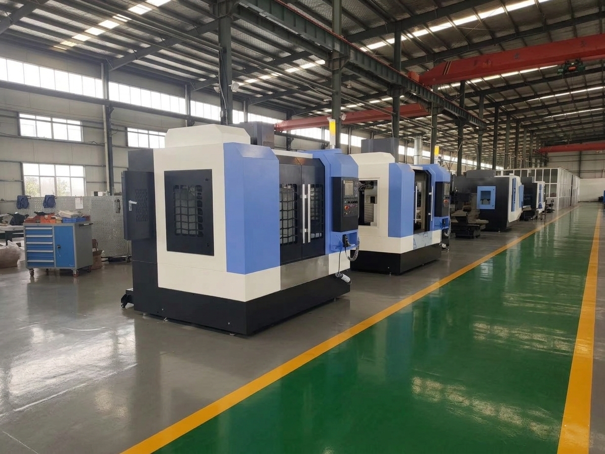
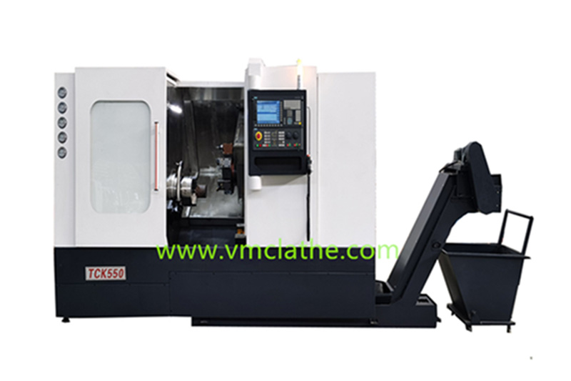
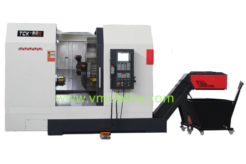
I. Why Choose a Slant-Bed CNC Lathe for Drive Shaft Machining?
Compared to traditional flat-bed CNC lathes, slant-bed CNC lathes (typically featuring a 30 degree, 45 degree , or 60 degree inclined guide rail) offer several critical advantages when processing shaft-type parts:
1. Superior Rigidity and Excellent Vibration Dampening
Drive shafts are generally long-shaft components that are highly susceptible to deformation and cutting vibrations during machining. The slant-bed structure provides a larger cross-sectional area for the lathe, significantly boosting its bending and torsional resistance. Furthermore, the cutting force aligns more closely with the direction of gravity, enabling smoother spindle operation and effectively suppressing tool chipping or chatter marks during long-shaft processing.
2. Smooth Chip Evacuation to Protect Workpiece Surfaces
The inclined bed design allows the massive volume of iron chips generated during cutting to slide naturally into the chip conveyor under gravity. This prevents chips from tangling around the drive shaft or the cutting tools, thereby ensuring high surface finish on the drive shaft’s outer diameter and preventing scratches.
3. High Precision and Thermal Stability
The ball screws and guide rails of a slant-bed lathe reside on different inclined planes. This effective thermal isolation and conduction design minimizes axial and radial thermal deformation caused by heat buildup during continuous machining. This is paramount for drive shafts that require strict dimensional tolerance control over journal positions, such as bearing seats and keyway sections.
II. Full Machining Process Workflow of Drive Shafts on Slant-Bed CNC Lathes
Drive shafts typically feature multi-step outer diameters, threads, keyways, undercut grooves, and tapers. The standard machining workflow can be broken down into the following core stages:
1. Blank Preparation and Pre-treatment
• Material Selection: Drive shafts are usually made of medium-carbon steel (such as 45# steel) or alloy structural steel (such as 40Cr, 20CrMnTi), shaped via forging or rough rolling based on design requirements.
• Preliminary Heat Treatment: Normalizing or quenching and tempering (Q&T) is performed to eliminate residual internal stresses within the blank and improve its machinability.
2. Establishing the Positioning Datum (Center Hole Drilling)
For long-shaft components, “double centers” or “one-chuck-one-center” represent the most classic positioning methods.
• Prior to turning, standard center holes must be drilled into both end faces of the blank. Serving as the precise datum for the entire machining process, the center holes maximize the coaxiality of the multi-step outer diameters.
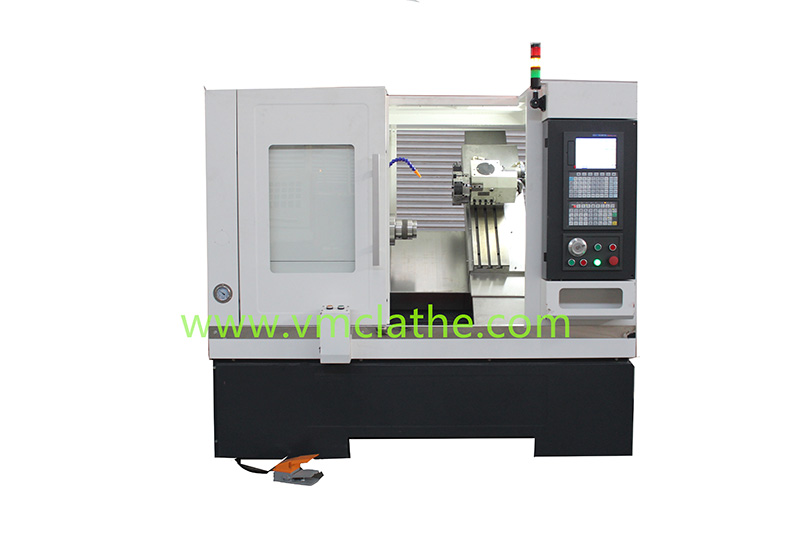
3. Workholding and Setup Design
Two primary workholding configurations are utilized on slant-bed CNC lathes:
• One-Chuck-One-Center: The spindle side uses a three-jaw self-centering chuck to grip one end of the drive shaft, while the tailstock employs a hydraulic live center to support the center hole at the opposite end. This is suitable for medium-length shafts.
• Double Centers with a Driving Dog: The spindle side is fitted with a dead center and a driving plate, while the tailstock utilizes a live center. This method yields the highest positioning accuracy, completely eliminating radial deformation caused by chuck clamping forces.
• Note: For ultra-long drive shafts with extreme length-to-diameter ratios, a follow rest or steady rest must be used during machining to support the shaft body and prevent bending triggered by cutting forces.
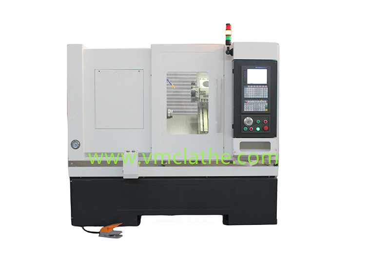
4. CNC Turning Stage
Efficient cutting is executed using the multi-station hydraulic turret of the slant-bed lathe:
• Rough Turning of Outer Diameters: Utilizing a large depth of cut and high feed rates, this stage removes the bulk of the machining allowance in layers. The high rigidity of the slant-bed supports elevated material removal rates during this phase.
• Semi-Fine Turning: This step leaves an appropriate allowance for subsequent heat treatment or grinding, corrects geometric deformations caused by rough turning, and cuts undercut grooves, chamfers, and transition radii.
• Finish Turning: Employing high spindle speeds, small feed rates, and coated carbide (or cermet) tools, this step finish-turns critical outer diameters like bearing and seal seats, directly guaranteeing dimensional tolerances and surface roughness.
• Thread Turning: If the end of the drive shaft requires connecting threads, multi-pass threading is executed utilizing the lathe’s thread-cutting cycles (such as G92 or G76 commands).
5. Secondary Machining and Surface Strengthening (If Applicable)
• Milling Keyways/Splines: If a slant-bed turn-mill center equipped with a C-axis/Y-axis live tooling turret is used, the milling of drive shaft keyways, splines, or end-face holes can be completed directly on the same machine. This achieves “process intensive integration” and eliminates concentricity errors caused by secondary setups.
• Surface Hardening and Grinding: After high-frequency induction hardening is applied to critical high-stress zones (such as journals), the shaft enters a cylindrical grinder for final precision grinding to attain the ultimate IT6 accuracy grade.
III. Industry Recommendations for Boosting Drive Shaft Machining Efficiency
To achieve optimal economic returns when machining drive shafts on slant-bed CNC lathes, the following practices are recommended:
• Select Tool Geometry Carefully: Positive rake angle inserts are highly recommended for shaft turning to reduce the radial cutting force , thereby minimizing the bending deformation of the shaft.
• Strictly Control Cutting Fluid Concentration: Maintain abundant cooling and lubrication to carry away heat promptly, preventing thermal expansion and contraction from disrupting the axial dimension chain of the shaft components.
• Prioritize Hydraulic Tailstocks: Utilize the CNC system to precisely regulate the tailstock clamping force. This prevents shaft bending caused by excessive force, as well as rigidity deficits caused by insufficient force.
Conclusion
With its exceptional structural rigidity, highly efficient chip evacuation, and outstanding precision retention, the slant-bed CNC lathe has become the ideal powerhouse for drive shaft machining. By implementing sound workholding strategies, maintaining strict datum control, and optimizing cutting parameters, manufacturers can unleash massive leaps in production capacity while fully securing the coaxiality and surface quality of their drive shafts.